the PHOTOSWITCH story - EXTENDED VERSION
Chapter 1: HELLO, MY NAME IS SLOBODAN AND I COMPLICATED MY LIFE BY DESIGNING AN OPTICAL FOOTSWITCH
If your guitar pedal isn’t turning on, chances are it’s the footswitch.
It is the most used (and abused) part of every guitar pedal and obviously the first to mechanically break. I remember finding the Lehle soft momentary switch on Banzai Music back in high school and buying one out of curiosity. I was amazed by how smooth it felt, how soft the spring was, and by how durable it was supposed to be. I am saying “supposed to be”, because I will probably never come close to testing its theoretical limits. It is still in my first generation Ditto looper, because the original switch - you guessed it - broke.
I like things that are built to last. And a component that gets stomped on constantly should definitely be one of them. So when I learned that GigRig use optical switches in their switchers, something clicked. If a company focused entirely on switching signals relies on optical footswitches, there’s probably a good reason.
That sent me down a rabbit hole. I went looking for datasheets, explanations, anything that would tell me how these switches actually work. There wasn’t much out there. So I turned to the next best thing: optical keyboard switches.
That’s where things started to make sense. At its core, an optical switch is surprisingly simple. You have a component that emits light, one that detects it, and something in between that interrupts the beam. Depending on how you set it up, the system reacts either when the light is present or when it’s blocked. I don’t know what I expected, tiny gremlins running around a small metal housing, playing with lasers… For some reason I was expecting this to be rocket science. Instead it was simple. Logical. Which meant I had no excuse not to try building one. Now all that was left was figuring out the circuit, the switching logic, and the mechanical design that would reliably interrupt that beam of light.
Chapter 2: PUTTING THE TRY IN GEOMETRY
The rough sketch came together quickly. In my mind there was only one way this could go - only one approach that made sense - so I ran with it. Here’s the tricky part: when you’re not a big company and your prototyping budget is limited, you try to solve as many problems as possible before anything gets made. Ordering even a single test piece isn’t cheap, so most of the work happens in your head or in CAD.
I tried to imagine every potential issue and deal with it upfront. But at some point, you just have to take the leap and order the first prototype.
So I did. And… I wasn’t happy.
The core idea worked - the basic principle was sound - but some of the details just didn’t translate into the real world. Features that were meant to eliminate alignment issues ended up making assembly unnecessarily complicated. The whole thing was slightly too large and, frankly, not very nice to look at.
Back to the drawing board. Or, more accurately, back to CAD.
This time, there was pressure. The goal was to fix everything in one more iteration and be done. The geometry got simplified, the shape cleaned up, and visually it was a big improvement. Functionality was already proven, so this felt like the final version. Second iteration. Done. I was impressed with myself.
But confirmation bias has a great sense of humor. It had been standing behind me the whole time, quietly watching and waiting.
Silly man. You did good - but not that good.
That realization would come much later.
Chapter 3: THE ELECTRONS DANCE
The mechanical design is only part of the story. An optical switch without the right circuitry is just a paperweight. It’s a dance for two - and it’s only as good as the weakest dancer.
On paper, the task sounded simple: create a switching circuit that reacts to the interruption of a light.
But there was no need to reinvent everything from scratch. Reliable switching circuits have been around for decades. So instead of complicating things further, I decided to adapt the classic Boss switching circuit to my needs.
I used a MOSFET to mimic the behavior of a momentary switch - pulling the signal to ground and triggering the change between ON and OFF states. That part was relatively straightforward.
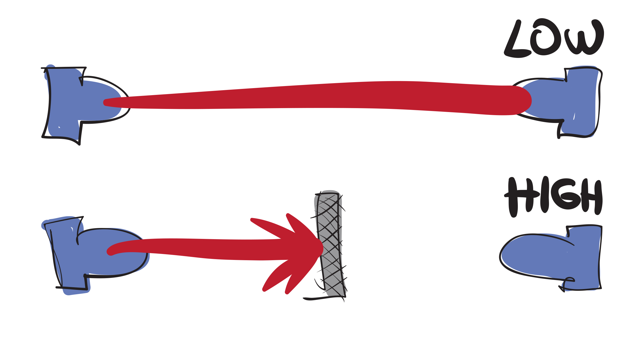
The question now was: how do I make the footswitch communicate with the circuit? The idea was simple. An infrared LED emits light toward a phototransistor. When the light reaches it, the transistor conducts and pulls a line LOW. When the beam is interrupted, the transistor stops conducting, and the line goes HIGH. In simple terms: light present = one state, light blocked = the other. That signal is then compared to a reference voltage using an op-amp configured as a comparator. The output of the op-amp controls the MOSFET, which in turn handles the switching. Nothing particularly exotic.
It just needed to be tuned - component values adjusted to keep current consumption low while maintaining stability and reliability.
And it worked. Under normal conditions, everything behaved exactly as expected. But I made a mistake. I was so focused on getting it to work that I didn’t spend enough time trying to break it.
You can get surprisingly far - maybe 80-85% - by testing normal operation. But the remaining 15% only shows up when you start thinking like a raccoon rummaging through trash, actively looking for ways to make things fail. The problem is… how do you find issues you haven’t even thought of? How do you look for something when you don’t know what you’re looking for?
You don’t. Eventually, those problems find you.
Chapter 4: A FOOTSWITCH FOR DUMMIES OR A FOOTSWITCH MADE BY A DUMMY
A good design works when operated as intended. A great design works even when it’s used in ways nobody could have predicted. But to get there, you first have to imagine those edge cases - or at least stumble into them.
I learned that lesson earlier with the Baker’s Dozen. Someone managed to fry the protection diode by using the wrong polarity power supply. The diode did its job and protected the circuit, but it left the pedal unusable until the diode was removed or replaced.
So I went back, reworked the power section, and ended up with a circuit that could handle a wider range of voltages and would simply shut itself off if something was out of spec - too low voltage, too high voltage, or reversed polarity. I wanted to apply the same philosophy to the footswitch and its circuitry. All I had to do was wait for the next problem to show up.
And for a while… nothing did. Everything worked as expected. No obvious issues. Until one day, while filming a demo for the Blue Whale, I got distracted and pressed the switch only halfway. Suddenly, it started oscillating rapidly between ON and OFF.
That was new. I grabbed another unit. Same behavior. Then I tried the Baker’s Dozen. No issue at all.
So now I had two pedals: one that worked perfectly, and one that only worked perfectly if you used it properly. That wasn’t good enough.
The issue didn’t show up during normal use - you had to deliberately find that awkward middle position and hold it there. But the fact that it could happen at all meant the design wasn’t finished.
So what changed? Ironically, it came from trying to improve something else.
I switched from through-hole optical components to surface-mount ones, mounting them directly on the switch to reduce alignment variability. On paper, the components were nearly identical. In reality, they weren’t identical enough.
That small change was enough to expose a flaw in the circuit. When I originally designed it, I hadn’t included hysteresis in the op-amp comparator. And because everything seemed to work, I never went back to question it. You can’t fix a problem if it doesn’t look like one.
Chapter 5: IT’S SCREWED IF IT’S UNSCREWED
I never received any complaints about the footswitch. As far as I could tell, the design was performing well. Then one day, I got an email from a customer. The footswitch had come apart.
The screw holding everything together had loosened, and the whole assembly disassembled itself. The fix was simple - just screw it back together. Then another email came in. Different customer. Same issue. At that point, it stopped being a coincidence. Something was wrong.
I had used threadlock on all the screws. At least, I thought I had. Had I missed something? Had I not tested it properly? How did this slip through?
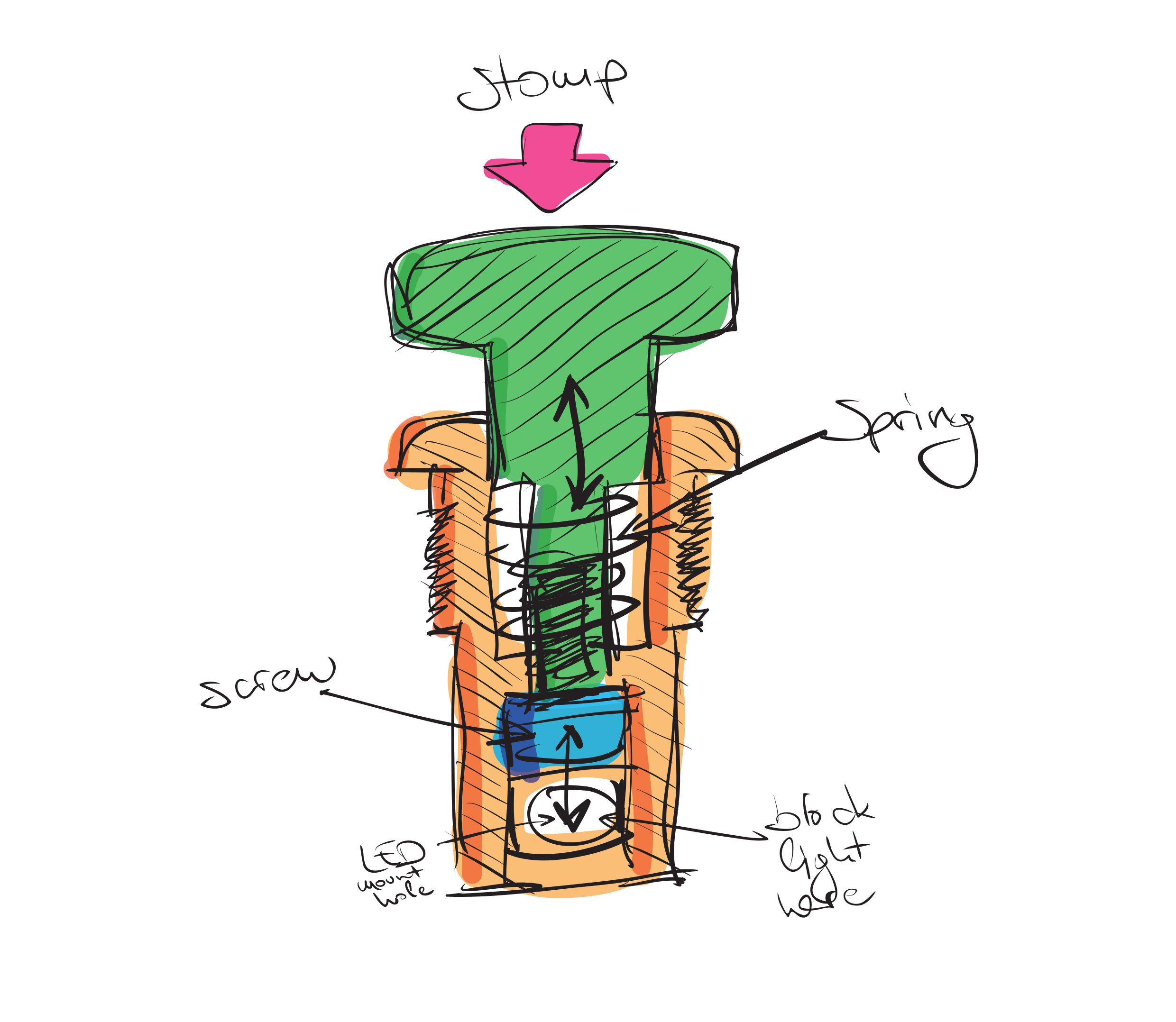
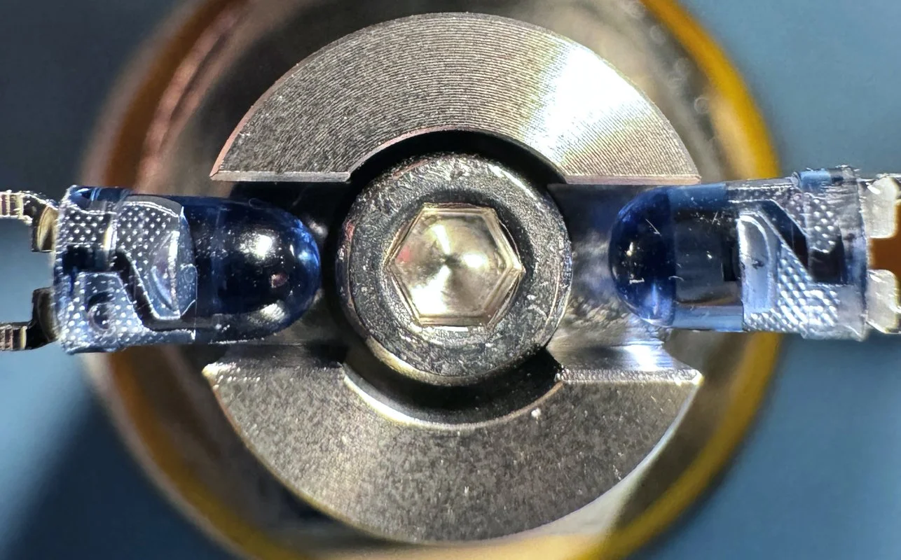
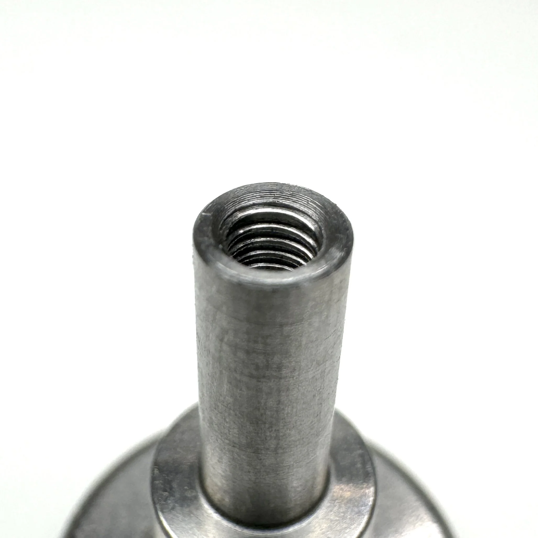
The design relied on a small screw to hold everything together and to interrupt the infrared beam. It seemed like an elegant solution - one part doing two jobs.
Threadlock had worked in testing. Some assemblies were locked so firmly they couldn’t be undone even with force. So I tried to double down on that approach. I bought a range of threadlock compounds - low strength, medium strength, high strength, different viscosities - and tested them on sacrificial parts. The results were… inconsistent.
Even with the same threadlock, some assemblies were permanently stuck, while others came apart with almost no effort. That was the turning point. Instead of trying to make the threadlock more reliable, I decided to remove the dependency on it altogether. No screw. No problem.
Around that time, a random memory resurfaced. About twenty years ago, I dropped my guitar because the strap slipped off. That’s when I discovered straplocks. I remember installing a set of Dunlop straplocks and struggling with that tiny C-shaped washer that holds everything in place. Putting it on was tricky. Realising you’ve put it the wrong way around was frustrating. Taking it off was a nightmare. Well, I need this part to be a nightmare to remove.
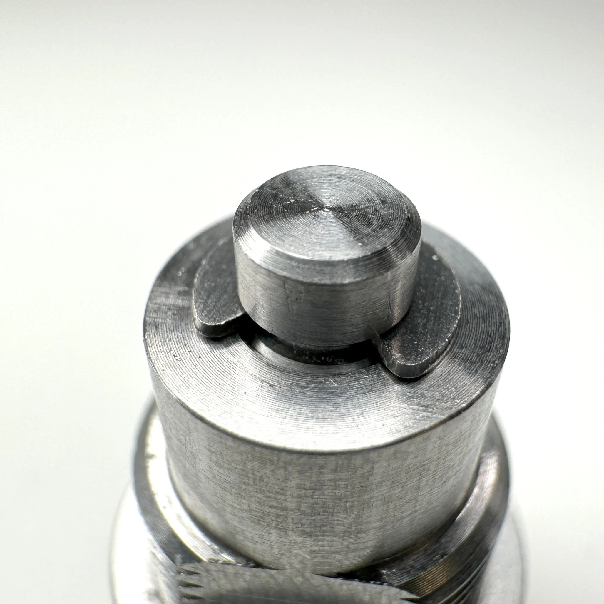
That little piece turned out to be an E-type circlip. So I started looking into whether something like that could work for my design. Turns out, it could.
I ordered a few for testing and designed a new prototype around them. The idea was simple: use a circlip mounted perpendicular to the direction of force, so normal operation wouldn’t cause it to come loose.
So far, the results are promising. It has survived repeated stomping tests, and even some less scientific methods involving a hammer. At this point, it might be the most reliable solution yet. But I’ve learned that it’s better not to celebrate too early.
Chapter 6: BUT… WHY??
That’s a fair question.
There are hundreds of switches on the market - cheap, expensive, soft click, hard click… pretty much every variation you can think of. There was no real need to design another one. And yet, I did it anyway.
It was never really about the footswitch itself. It was about the challenge. About seeing where the limits were, and whether I could push past them. How far can you go when you step into something you don’t fully understand yet? That was the interesting part.
At the same time, I do think the result is genuinely interesting. It looks different. It behaves differently. And once all the weak points are ironed out, it should be very durable.
But more than anything, it was about the process. It was frustrating at times. Expensive. Occasionally confusing. But also deeply satisfying in a way that’s hard to explain unless you’ve gone through it yourself.
And it’s not really finished. It feels like the design is converging toward something final - but it has felt that way before. So for now, it’s still evolving. And I’m still learning from it.
Looking back, it’s a lot of time and effort spent on something most people will never notice. But that’s kind of the point.
When it works the way it should, it disappears. And that’s when you know you got it right.